

Broad Band Horn Antenna View More
Connical horn antenna View More
Double Polarization Horn Antenna View More

Millimeter SGH Antenna View More
Standard Gain Horn Antenna View More
Curve Standard Gain Horn Antenna View More
Multi Octave Horn Antenna View More

Broad Band Horn Antenna View More
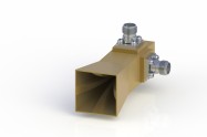
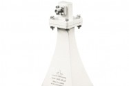
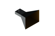
Why wideband double ridged horn antennas
There has been an increasing interest in applying wideband double ridged horn antennas in EMC test procedures because of their high gain, well-shaped beam, and easy manufacturing.
Dual ridged horn antennas became commercially available, and some standards like MILSTD-461E determined 1-18 GHz dual-ridged horn as the standard antenna for the EMC test procedures.
Applications:
EMC/RF Measurements
Detecting the Direction
Surveillance
Antenna Gain/Pattern Measurements
The frequency range of dual-ridged horn antenna
The compact design of an ultra
wideband dual ridged horn antenna (DRHA)。The antenna
operates wide band with a peak gain of about 16 dBi. It is one of the most common aperture antenna used in laboratories mainly operated in the L-band S-band C-band, X-band,K-band, Ku-band, and Ka-band, E-band (0.2GHz to 50GHz).OBH series antennas support linear polarized waveforms and appropriate for the test of wireless and telecom communication.
Why double ridge
To extend the maximum usage of the bandwidth of horns, ridges are introduced in the flared part of the antenna. This is commonly done in waveguides to lower the fundamental mode's cutoff frequency and thus expand the single-mode range before higher-order modes occur.
One common kind of ridged horn antenna is the double-ridged antenna.
Four important parts a dual-ridged horn have
A Double ridge horn antenna contains four main sub-sections:
Feeding section,
waveguide
back cavity section, ridges,
the pyramidal Figure shows the perspective view and
the cut-away view of the understudy DRHA.
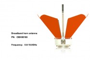
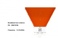
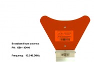
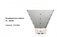
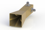
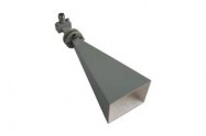
The ECmicrowave broadband horn antenna presents a very low VSWR in its minor frequency range and ultra broad bandwidth. The increasing gain with frequency helps to compensate for cable losses. This horn antenna only supports linear polarization and can be used for receiving and transmitting applications.
The broadband horn antenna covers the frequency range from 0.1GHz to 40GHz with the gain from 4 dBi to 20 dBi VSWR is <2.7Max and a Single Linear Polarization.
The antenna is appropriate for the test of wireless and telecom communication antennas. High gain and low VSWR permit the measurement of weak signals and the generation of high field strengths without any significant return loss
| Part No | Frequency Range(GHz) | Gain(dBi) | VSWR | Polarization | Cross-Polar Discrimination | Impedance |
| OBH-230 | 0.2 - 3.0 | 6-15 | <2.0Max | Single Linear | 50Ω | 50Ohms |
| OBH-460 | 0.4-6.0 | 6-15 | <2.0Max | Single Linear | 50Ω | 50Ohms |
| OBH-690 | 0.6 - 9.0 | 6-15 | <2.0Max | Single Linear | 50Ω | 50Ohms |
| OBH80D-15 | 0.8 - 2.0 | 10-16 | <2.0Max | Single Linear | 50Ω | 50Ohms |
| OBH-880 | 0.8 - 8.0 | 8-13 | <2.7Max | Single Linear | 50Ω | 50Ohms |
| OBH-08120 | 0.8 - 12.0 | 6-15 | <2.0Max | Single Linear | 50Ω | 50Ohms |
| OBH-08180 | 0.8-18.0 | 8-13 | <2.7Max | Single Linear | 50Ω | 50Ohms |
| OBH-1020-15 | 1-2 | 15 | 2.0 Max. | Linear | 50Ω | 50Ohms |
| OBH-10125 | 1.0-12.5 | 6-15 | <2.0Max | Single Linear | 50Ω | 50Ohms |
| OBH-10180 | 1.0-18.0 | 6-15 | <2.0Max | Single Linear | 50Ω | 50Ohms |
| OBH-200D-15 | 2-4.8 | 15 | 2.0 Max. | Linear | 50Ω | 50Ohms |
| OBH-20180 | 2.0 - 18.0 | 3.5-13 | <2.0Max | Single Linear | 50Ω | 50Ohms |
| OBH-20200 | 2.0 - 20.0 | 3.5-13 | <2.0Max | Single Linear | 50Ω | 50Ohms |
| OBH-20320 | 2.0 - 32.0 | 4-16 | <2.0Max | Single Linear | 50Ω | 50Ohms |
| OBH-750D-15 | 7.5-18 | 15 | 2.0 Max. | Linear | 50Ω | 50Ohms |
| OBH-100400 | 10.0-40.0 | 8-13 | <2.7Max | Single Linear | 50Ω | 50Ohms |
| OBH-110D-15 | 11-26.5 | 15 | 2.0 Max. | Linear | 50Ω | 50Ohms |
| OBH-180400 | 18-40.0 | 4-16 | <2.0Max | Single Linear | 50Ω | 50Ohms |
| OBH-180500 | 18-50.0 | 13-17 | 1.2:1 | Linear | 50Ω | 50Ohms |
Connical horn antenna View More
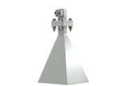
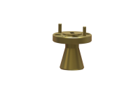
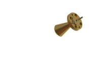
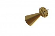
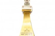
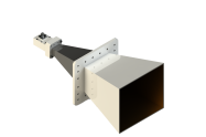
Conical Horns
What is conical Horn antenna
An efficient microwave antenna is a conical horn shown in the Figure below.
The waveguide of the conical horn antenna different from the pyramidal horn antenna
While the pyramidal, E-, and H-plane sectoral horns are usually fed by a rectangular
waveguide, the feed of a conical horn is often a circular waveguide or rectangular waveguide.
Directivity of a conical horn
Directivity of a conical horn as a function of aperture diameter and for different axial horn lengths.
Radiation Pattern
A comparison of both radiation
patterns can be found in Figure, where it can be seen that both horns have good
radiation pattern characteristics.
Conical Horn Antenna is presented as both standard and custom models with either a circular or rectangular waveguide interface. Circular waveguide interface can support many polarization kinds counting horizontal, vertical, left-handed circular, and right-handed circular polarization for wider applications, while Conical Horn Antennas with a rectangular waveguide interface can only support linear polarization.
Conical Horn Antennas can be considered to be a waveguide that has been broadened out in the form of a horn. As a product, it finds many applications in areas where waveguides are used.
Conical Horn forms a flat change between the waveguide and free space whilst also pointing the radio waves in a beam. Conical Horn Antenna display better reflectivity levels in the quiet zone of tapered chambers, with low VSWR across the range. Conical Horn Antennas covers the frequency range from 50GHz to 140GHz, standard gain from 14dbi to 25dbi, and VSWR is 1.15:1.
Double Polarization Horn Antenna View More
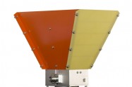
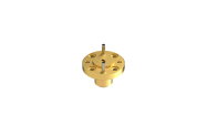
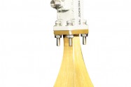
Double Polarization Horn Antenna
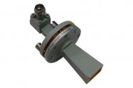
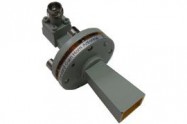
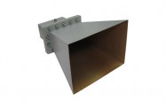
The use of ultra-wideband (UWB) antenna technologies for the UWB radar and communication systems in both military and civilian applications continues to increase, In some high power radar system, high gain and stable phase center is very important, and the ridged horn is very proper for this application. The dual-polarization system can get more information than the single-polarization antenna system; furthermore, the polarization modes at different directions using one radiation aperture make the structure more compaction. So realizing dual-polarization antenna by loading quad-ridged with proper feeding is very important. The quad-ridged horn antenna can employ the dual-polarization character.
The fabricated QRHA unit had an offset feed semi-rigid (50 Ω) coax to waveguide transition using a captivated coaxial female connector. The semi-rigid coax passes through the center of the ridge, and only the inner conductor is exposed in the ridge gap, which terminates in the alignment cavity present on the opposite ridge. A similar orthogonal probe is present for the other pair of ridges having a center to center offset with reference to the first probe.
Dual polarized horn antennas (quad ridged horn antenna) are offered as both standard and custom models with rectangular waveguide borders for both plane and vertical ports. Dual polarized horn antennas support the linear polarized waveforms.
Dual polarized horn antennas offer frequencies of 1GHz to 3GHz, 2GHz to 6GH-z, 6GHz to 18GHz, 18GHz to 40GHz, 22GHz to 44GHz with a nominal gain of 8-20dBi. The impedance of 50 Ohms. In Dual polarized horn antennas connections, the type is 2.92mm Connectors, SMA Connectors, or N connectors.
Millimeter SGH Antenna View More
Standard Gain Horn Antenna View More
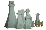
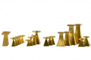
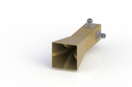
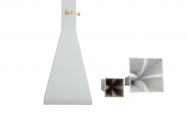
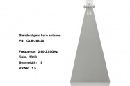
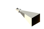
Pyramidal Standard-Gain Horn antenna/ Standard-Gain Horns
Applications
Accurate antenna gain measurements are essential in a wide range of applications
such as satellite communications, remote sensing, electromagnetic compatibility measurements,
and radar.
To evaluate the gain of an antenna, it is customary to compare
its performance against a well-calibrated “standard.” So-called standard-gain horns are
used for this purpose.
A standard-gain horn antenna can be used to
1. standard for calibrating other antennas
2. feed for reflectors and lenses
3. pickup (probe) horn for sampling power
4. receiving and/or transmitting antenna.
What is Pyramidal Standard-Gain Horn antenna
The most common type of horn used as a standard-gain horn is the pyramidal horn
shown in the figure below

The rectangular geometry of this horn
enables easy manufacture and results in a low-cost antenna.
The key specifications to choose a standard-gain horn antenna
The fields radiated by a pyramidal horn
The fields radiated by a pyramidal horn, as given by the figure below, are valid for all angles of observation.
Directivity
Directivity is one of the parameters that is often used as a figure of merit to
describe the performance of an antenna. To find the directivity, the maximum radiation
is formed.
The overall performance of an antenna system can often be judged by its beamwidth
and/or its directivity.
Gain
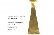
Gains of the pyramidal horn which were measured, provided by RFecho, The amplitude patterns of the horn are shown in the figure below.
| Part No. | Frequency Range(GHz | Gain(dB) | 3dB Beam Width | Waveguide | Material | Polarization | Impedance | Waveguide Size |
| OLB-34-20 | 22.0-33.0 | 20 | H 18° / V 18° | WR34 | Cu | Linear | 50O | WR-34 Waveguide with UG-1530/U Flange |
| OLB-34-25 | 22.0-33.0 | 25 | H 10° / V 10° | WR34 | Cu | Linear | 50O | WR-34 Waveguide with UG-1530/U Flange |
| OLB-42-15 | 18.0-26.5 | 15 | H 30° / V 30° | WR42 | Cu | Linear | 50O | WR-42 Waveguide with UG-595/U Flange |
| OLB-42-20 | 18.0-26.5 | 20 | H 18° / V 18° | WR42 | Cu | Linear | 50O | WR-42 Waveguide with UG-595/U Flange |
| OLB-51-15 | 15.0-22.0 | 15 | H 30° / V 30° | WR51 | Cu | Linear | 50O | WR-51 Waveguide with UG-387/U Flange |
| OLB-62-15 | 11.9-18.0 | 15 | H 30° / V 30° | WR62 | Cu | Linear | 50O | WR-62 Waveguide with UG-419/U Flange |
| OLB-75-15 | 10.0-15.0 | 15 | H 30° / V 30° | WR75 | AI | Linear | 50O | WR-75 Waveguide with UG-387/U-M Flange |
| OLB-75-20 | 10.0-15.0 | 20 | H 18° / V 18° | WR75 | AI | Linear | 50O | WR-75 Waveguide with UG-387/U-M Flange |
| OLB-90-15 | 8.2-12.5 | 15 | H 30° / V 30° | WR95 | AI | Linear | 50O | WR-90 Waveguide with UG-39/U Flange |
| OLB-90-20 | 8.2-12.5 | 20 | H 18° / V 18° | WR95 | AI | Linear | 50O | WR-90 Waveguide with UG-39/U Flange |
| OLB-112-15 | 7.5-10.0 | 15 | H 30° / V 30° | WR112 | AI | Linear | 50O | WR-112 Waveguide with PDF84 |
| OLB-137-10 | 5.85-8.20 | 10 | H 55° / V 55° | WR137 | AI | Linear | 50O | WR-137 Waveguide with PDF70 |
| OLB-137-15 | 5.85-8.20 | 15 | H 30° / V 30° | WR137 | AI | Linear | 50O | WR-137 Waveguide with PDF70 |
| OLB-137-20 | 5.85-8.20 | 20 | H 18° / V 18° | WR137 | AI | Linear | 50O | WR-137 Waveguide with PDF70 |
| OLB-159-10 | 4.90-7.05 | 10 | H 55° / V 55° | WR159 | AI | Linear | 50O | WR-159 Waveguide with PDF58 |
| OLB-159-15 | 4.90-7.05 | 15 | H 30° / V 30° | WR159 | AI | Linear | 50O | WR-159 Waveguide with PDF58 |
| OLB-159-20 | 4.90-7.05 | 20 | H 18° / V 18° | WR159 | AI | Linear | 50O | WR-159 Waveguide with PDF58 |
| OLB-187-20 | 3.95-5.85 | 20 | H 18° / V 18° | WR187 | AI | Linear | 50O | WR-187 Waveguide with PDF48 |
| OLB-284-15 | 2.60-3.95 | 15 | H 30° / V 30 | WR284 | AI | Linear | 50O | WR-284 Waveguide with PDF32 |
| OLB-284-20 | 2.60-3.95 | 20 | H 18° / V 18° | WR284 | AI | Linear | 50O | WR-284 Waveguide with PDF32 |
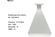
| OLB-340-10 | 2.20-3.30 | 10 | H 55° / V 55° | WR340 | AI | Linear | 50O | WR-340 Waveguide with PDF26 |
| OLB-340-20 | 2.20-3.30 | 20 | H 18° / V 18° | WR340 | AI | Linear | 50O | WR-340 Waveguide with PDF26 |
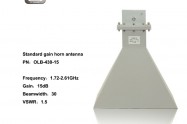
| OLB-430-15 | 1.72-2.61 | 15 | H 30° / V 30° | WR430 | AI | Linear | 50O | WR-430 Waveguide with PDF22 |
| OLB-430-20 | 1.72-2.61 | 20 | H 18° / V 18° | WR430 | AI | Linear | 50O | WR-430 Waveguide with PDF22 |
| OLB-650-15 | 1.12-1.17 | 15 | H 30° / V 30° | WR650 | AI | Linear | 50O | WR-650 Waveguide with PDF14 |
| OLB-770-15 | 0.96-1.45 | 15 | H 30° / V 30° | WR770 | AI | Linear | 50O | WR770 Waveguide with PDF12 |