


Horn Antenna View More

EMC Antenna View More
Broad Band Horn Antenna View More

Millimeter SGH Antenna View More


Back Cavity Spiral Antenna View More

Luneburg lens Antenna View More


Probe Antenna View More
SECTION View More
Double Polarization Horn Antenna View More

Log Periodic antenna View More


Biconical antena View More


Field Antennas View More


Antenna Mount And Accessories View More
Horn Antenna View More
EMC Antenna View More
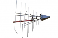
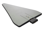
EMC ANTENNA
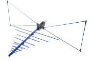
EC Microwave High Gain Log-Periodic Antenna offers excellent broadband characteristics, aradiation pattern that is approximately rotation-symmetrical as well as high gain, making itparticularly suitable for EMS immunity measurements. In comparison with existing systems, the required field strengths can be achieved with a lower amplifier power. This is due to the high antenna gain. Its small size, wide frequency range and folding mechanism make the antenna ideal for use in test chambers.
| PN | MIN Frequency | MAX Frequency | VSWR | Gain | Polarization | Impedance | Connector | PatternType |
| OVLA-00710 | 70MHz | 10GHz | <2 | 8.6dBi±2.3dB | Linear | 50Ωnominal | Type N female / Type 7/16 female | directional |
| OVLA-00810 | 80MHz | 1GHz | 1.5:1 average | 8 dBi | Linear | 50Ωnominal | Type 7/16 female | directional |
| OVLA-00815 | 80MHz | 1.5GHz | <1.5 | 9 +0.8 / -1.5 dB | Linear | 50Ωnominal | Type N female / Type 7/16 female | directional |
| OVLA-0083 | 80MHz | 3GHz | <2 | >8dBi | Linear | 50Ωnominal | Type N female | directional |
| OVLA-008100 | 80MHz | 10GHz | <2 | 8.1dBi±2.8dB | Linear | 50Ωnominal | Type N female | directional |
| OVLA-06105 | 600MHz | 10.5GHz | <2 | 10.3 dBi +/- 1.5 dBi | linear | 50Ωnominal | Type N female | directional |
Broad Band Horn Antenna View More
Why wideband double ridged horn antennas
There has been an increasing interest in applying wideband double ridged horn antennas in EMC test procedures because of their high gain, well-shaped beam, and easy manufacturing.
Dual ridged horn antennas became commercially available, and some standards like MILSTD-461E determined 1-18 GHz dual-ridged horn as the standard antenna for the EMC test procedures.
Applications:
EMC/RF Measurements
Detecting the Direction
Surveillance
Antenna Gain/Pattern Measurements
The frequency range of dual-ridged horn antenna
The compact design of an ultra
wideband dual ridged horn antenna (DRHA)。The antenna
operates wide band with a peak gain of about 16 dBi. It is one of the most common aperture antenna used in laboratories mainly operated in the L-band S-band C-band, X-band,K-band, Ku-band, and Ka-band, E-band (0.2GHz to 50GHz).OBH series antennas support linear polarized waveforms and appropriate for the test of wireless and telecom communication.
Why double ridge
To extend the maximum usage of the bandwidth of horns, ridges are introduced in the flared part of the antenna. This is commonly done in waveguides to lower the fundamental mode's cutoff frequency and thus expand the single-mode range before higher-order modes occur.
One common kind of ridged horn antenna is the double-ridged antenna.
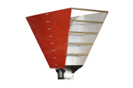
Four important parts a dual-ridged horn have
A Double ridge horn antenna contains four main sub-sections:
Feeding section,
waveguide
back cavity section, ridges,
the pyramidal Figure shows the perspective view and
the cut-away view of the understudy DRHA.
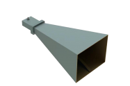
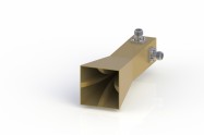
The ECmicrowave broadband horn antenna presents a very low VSWR in its minor frequency range and ultra broad bandwidth. The increasing gain with frequency helps to compensate for cable losses. This horn antenna only supports linear polarization and can be used for receiving and transmitting applications.
The broadband horn antenna covers the frequency range from 0.1GHz to 40GHz with the gain from 4 dBi to 20 dBi VSWR is <2.7Max and a Single Linear Polarization.
The antenna is appropriate for the test of wireless and telecom communication antennas. High gain and low VSWR permit the measurement of weak signals and the generation of high field strengths without any significant return loss
| Part No | Frequency Range(GHz) | Gain(dBi) | VSWR | Polarization | Cross-Polar Discrimination | Impedance |
| OBH-230 | 0.2 - 3.0 | 6-15 | <2.0Max | Single Linear | 50Ω | 50Ohms |
| OBH-460 | 0.4-6.0 | 6-15 | <2.0Max | Single Linear | 50Ω | 50Ohms |
| OBH-690 | 0.6 - 9.0 | 6-15 | <2.0Max | Single Linear | 50Ω | 50Ohms |
| OBH80D-15 | 0.8 - 2.0 | 10-16 | <2.0Max | Single Linear | 50Ω | 50Ohms |
| OBH-880 | 0.8 - 8.0 | 8-13 | <2.7Max | Single Linear | 50Ω | 50Ohms |
| OBH-08120 | 0.8 - 12.0 | 6-15 | <2.0Max | Single Linear | 50Ω | 50Ohms |
| OBH-08180 | 0.8-18.0 | 8-13 | <2.7Max | Single Linear | 50Ω | 50Ohms |
| OBH-1020-15 | 1-2 | 15 | 2.0 Max. | Linear | 50Ω | 50Ohms |
| OBH-10125 | 1.0-12.5 | 6-15 | <2.0Max | Single Linear | 50Ω | 50Ohms |
| OBH-10180 | 1.0-18.0 | 6-15 | <2.0Max | Single Linear | 50Ω | 50Ohms |
| OBH-200D-15 | 2-4.8 | 15 | 2.0 Max. | Linear | 50Ω | 50Ohms |
| OBH-20180 | 2.0 - 18.0 | 3.5-13 | <2.0Max | Single Linear | 50Ω | 50Ohms |
| OBH-20200 | 2.0 - 20.0 | 3.5-13 | <2.0Max | Single Linear | 50Ω | 50Ohms |
| OBH-20320 | 2.0 - 32.0 | 4-16 | <2.0Max | Single Linear | 50Ω | 50Ohms |
| OBH-750D-15 | 7.5-18 | 15 | 2.0 Max. | Linear | 50Ω | 50Ohms |
| OBH-100400 | 10.0-40.0 | 8-13 | <2.7Max | Single Linear | 50Ω | 50Ohms |
| OBH-110D-15 | 11-26.5 | 15 | 2.0 Max. | Linear | 50Ω | 50Ohms |
| OBH-180400 | 18-40.0 | 4-16 | <2.0Max | Single Linear | 50Ω | 50Ohms |
| OBH-180500 | 18-50.0 | 13-17 | 1.2:1 | Linear | 50Ω | 50Ohms |
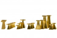
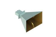
Millimeter SGH Antenna View More
| Part No. | Frequency Range(GHz) | Gain(dB) | 3dB Beam Width | Waveguide | Material | Polarization | Impedance | Waveguide Size |
| OLB-03-20 | 220-325 | 20 | H 18° / V 18° | WR3 | Cu | Linear | 50O | WR-03 Waveguide with UG-387/U-M Flange |
| OLB-03-25 | 220-325 | 25 | H 10° / V 10° | WR3 | Cu | Linear | 50O | WR-03 Waveguide with UG-387/U-M Flange |
| OLB-04-25 | 170-260 | 25 | H 10° / V 10° | WR4 | Cu | Linear | 50O | WR-04 Waveguide with UG-387/U-M Flange |
| OLB-05-20 | 140-220 | 20 | H 18° / V 18° | WR5 | Cu | Linear | 50O | WR-05 Waveguide with UG-387/U-M Flange |
| OLB-05-25 | 140-220 | 25 | H 10° / V 10° | WR5 | Cu | Linear | 50O | WR-05 Waveguide with UG-387/U-M Flange |
| OLB-06-10 | 110-170 | 10 | H 55° / V 55° | WR6 | Cu | Linear | 50O | WR-06 Waveguide with UG-387/U-M Flange |
| OLB-06-20 | 110-170 | 20 | H 18° / V 18° | WR6 | Cu | Linear | 50O | WR-06 Waveguide with UG-387/U-M Flange |
| OLB-06-23 | 110-170 | 23 | E 11° / H 13° | WR6 | Cu | Linear | 50O | WR-06 Waveguide with UG-387/U-M Flange |
| OLB-06-25 | 110-170 | 25 | H 10° / V 10° | WR6 | Cu | Linear | 50O | WR-06 Waveguide with UG-387/U-M Flange |
| OLB-08-20 | 90-140 | 20 | H 18° / V 18° | WR8 | Cu | Linear | 50O | WR-08 Waveguide with UG-387/U-M Flange |
| OLB-08-23 | 90-140 | 23 | E 11° / H 13° | WR8 | Cu | Linear | 50O | WR-08 Waveguide with UG-387/U-M Flange |
| OLB-08-25 | 90-140 | 25 | H 10° / V 10° | WR8 | Cu | Linear | 50O | WR-08 Waveguide with UG-387/U-M Flange |
| OLB-10-15 | 75-110 | 15 | H 30° / V 30° | WR10 | Cu | Linear | 50O | WR-10 Waveguide with UG-387/U-M Flange |
| OLB-10-20 | 75-110 | 20 | H 18° / V 18° | WR10 | Cu | Linear | 50O | WR-10 Waveguide with UG-387/U-M Flange |
| OLB-10-23 | 75-110 | 23 | E 11° / H 13° | WR10 | Cu | Linear | 50O | WR-10 Waveguide with UG-387/U-M Flange |
| OLB-10-25 | 75-110 | 25 | H 10° / V 10° | WR10 | Cu | Linear | 50O | WR-10 Waveguide with UG-387/U-M Flange |
| OLB-12-10 | 60-90 | 10 | H 55° / V 55° | WR12 | Cu | Linear | 50O | WR-12 Waveguide with UG-387/U Flange |
| OLB-12-13 | 60-90 | 13 | E 39° / H 41° | WR12 | Cu | Linear | 50O | WR-12 Waveguide with UG-387/U Flange |
| OLB-12-15 | 60-90 | 15 | H 30 °/ V 30° | WR12 | Cu | Linear | 50O | WR-12 Waveguide with UG-387/U Flange |
| OLB-12-20 | 60-90 | 20 | H 18° / V 18° | WR12 | Cu | Linear | 50O | WR-12 Waveguide with UG-387/U Flange |
| OLB-12-23 | 60-90 | 23 | E 11° / H 13° | WR12 | Cu | Linear | 50O | WR-12 Waveguide with UG-387/U Flange |
| OLB-12-25 | 60-90 | 25 | H 10° / V 10° | WR12 | Cu | Linear | 50O | WR-12 Waveguide with UG-387/U Flange |
| OLB-15-15 | 50-75 | 15 | H 30° / V 30° | WR15 | Cu | Linear | 50O | WR-15 Waveguide with UG-385/U Flange |
| OLB-15-17 | 50-75 | 17 | E 26° / H 25° | WR15 | Cu | Linear | 50O | WR-15 Waveguide with UG-385/U Flange |
| OLB-15-20 | 50-75 | 20 | H 18° / V 18° | WR15 | Cu | Linear | 50O | WR-15 Waveguide with UG-385/U Flange |
| OLB-15-23 | 50-75 | 23 | E 11° / H 13° | WR15 | Cu | Linear | 50O | WR-15 Waveguide with UG-385/U Flange |
| OLB-15-25 | 50-75 | 25 | H 10° / V 10° | WR15 | Cu | Linear | 50O | WR-15 Waveguide with UG-385/U Flange |
| OLB-19-10 | 40-60 | 10 | H 55° / V 55° | WR19 | Cu | Linear | 50O | WR-19 Waveguide with UG-383/U-M Flange |
| OLB-19-15 | 40-60 | 15 | H 30° / V 30° | WR19 | Cu | Linear | 50O | WR-19 Waveguide with UG-383/U-M Flange |
| OLB-19-17 | 40-60 | 17 | H 25° / V 25° | WR19 | Cu | Linear | 50O | WR-19 Waveguide with UG-383/U-M Flange |
| OLB-19-20 | 40-60 | 20 | H 18° / V 18° | WR19 | Cu | Linear | 50O | WR-19 Waveguide with UG-383/U-M Flange |
| OLB-19-23 | 40-60 | 23 | E 11° / H 13° | WR19 | Cu | Linear | 50O | WR-19 Waveguide with UG-383/U-M Flange |
| OLB-19-25 | 40-60 | 25 | H 10° / V 10° | WR19 | Cu | Linear | 50O | WR-19 Waveguide with UG-383/U-M Flange |
| OLB-22-20 | 33-50 | 20 | H 18° / V 18° | WR22 | Cu | Linear | 50O | WR-22 Waveguide with UG-383/U Flange |
| OLB-22-23 | 33-50 | 23 | E 11° / H 13° | WR22 | Cu | Linear | 50O | WR-22 Waveguide with UG-383/U Flange |
| OLB-22-25 | 33-50 | 25 | H 10° / V 10° | WR22 | Cu | Linear | 50O | WR-22 Waveguide with UG-383/U Flange |
| OLB-28-10 | 26.5-40 | 10 | H 55° / V 55° | WR28 | Cu | Linear | 50O | WR-28 Waveguide with UG-599/U Flange |
| OLB-28-17 | 26.5-40 | 17 | E 26° / H 25° | WR28 | Cu | Linear | 50O | WR-28 Waveguide with UG-599/U Flange |
| OLB-28-20 | 26.5-40 | 20 | H 18° / V 18° | WR28 | Cu | Linear | 50O | WR-28 Waveguide with UG-599/U Flange |
| OLB-28-23 | 26.5-40 | 23 | E 11° / H 13° | WR28 | Cu | Linear | 50O | WR-28 Waveguide with UG-599/U Flange |
| OLB-28-25 | 26.5-40 | 25 | H 10° / V 10° | WR28 | Cu | Linear | 50O | WR-28 Waveguide with UG-599/U Flange |
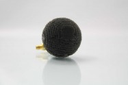
Back Cavity Spiral Antenna View More
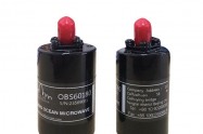
| Part No. | Frequency(GHz) | Nominal Gain3 dB | VSWR | Input Impedance | Connector | Porlarization | ax |
| OBS-520 | 0.5-2.0 | 3.6 Typ~6.1Typ | 2.5:1Maximum 2.0:1 Typical | 50 Ohms Nominal | N-female | LHCP/RHCP | <3dB |
| OBS-840 | 0.8-4.0 | 0.6 Typ~2.2Typ | 2.5:1Maximum 2.0:1 Typical | 50 Ohms Nominal | SMA-female | LHCP/RHCP | <3dB |
| OBS1080 | 1-8 | -3 Typ~1 Typ16° | 2.5:1Maximum 2.0:1 Typical | 50 Ohms Nominal | SMAfemale | LHCP/RHCP | <3dB |
| OBS-10180 | 1-18 | -3.5 Typ~5.3 Typ | 2.5:1Maximum 2.0:1 Typical | 50 Ohms Nominal | SMA-female | LHCP/RHCP | <3dB |
| OBS2040 | 2-4 | -3 Typ~1 Typ16° | 2.5:1Maximum 2.0:1 Typical | 50 Ohms Nominal | SMAfemale | LHCP/RHCP | <3dB |
| OBS-2060 | 2-6 | -3.2 Typ~3.8 Typ | 2.5:1Maximum 2.0:1 Typical | 50 Ohms Nominal | SMA-female | LHCP/RHCP | <3dB |
| OBS20180 | 2-18 | -3 Typ~1 Typ16° | 2.5:1Maximum 2.0:1 Typical | 50 Ohms Nominal | SMAfemale | LHCP/RHCP | <3dB |
| OBS-4080 | 4.0-8.0 | 2.5 Typ~5.6Typ | 2.5:1Maximum 2.0:1 Typical | 50 Ohms Nominal | SMA-female | LHCP/RHCP | <3dB |
| OBS-60180 | 6.0-18.0 | 2.5:1Maximum 2.0:1 Typical | 50 Ohms Nominal | SMA-female | LHCP/RHCP | <3dB | |
| OBS-80180 | 8-18.0 | 1.4 Typ~3.7 Typ | 2.5:1Maximum 2.0:1 Typical | 50 Ohms Nominal | SMA-female | LHCP/RHCP | <3dB |
| OBS-180265 | 18-26.5 | -4 Typ | 2.5:1Maximum 2.0:1 Typical | 50 Ohms Nominal | SMA-female | LHCP/RHCP | <3dB |
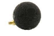
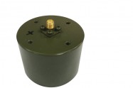
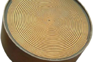
Luneburg lens Antenna View More
| Part No. | Frequency Range (GHz) | Gain (dB) | Return Loss (dB) | Beamwidth | Polarization | Diameter dimensions | Antenna weight |
| OLLA-1726 | 1.7-2.6 | 15 dBi | <-20 dB | 30degree@2.2GHz | All polarizations | 150mm | 120g |
| OLLA-2233 | 2.2-3.3 | 20 dBi | <-20 dB | 18degree@2.8GHz | All polarizations | 150mm | 120g |
| OLLA-2640 | 2.6-3.95 | 15 dBi | <-20 dB | 30degree@3.3GHz | All polarizations | 145mm | 116g |
| OLLA-4060 | 3.94-5.99 | 20 dBi | <-20 dB | 18degree @ 5GHz | All polarizations | 140mm | 112g |
| OLLA-4670 | 4.64-7.05 | 15 dBi | <-20 dB | 30degree@5.8GHz | All polarizations | 140mm | 112g |
| OLLA-5482 | 5.38-8.17 | 15 dBi | <-20 dB | 30degree@6.7GHz | All polarizations | 135mm | 108g |
| OLLA-66100 | 6.57-9.99 | 15 dBi | <-20 dB | 30 degree@8.2GHz | All polarizations | 130mm | 104g |
| OLLA-82125 | 8.2-12.5 | 15 dBi | <-20 dB | 30 degree @ 10GHz | All polarizations | 120mm | 96g |
| OLLA-98150 | 9.84-15 | 20 dBi | <-20 dB | 18degree@12.5GHz | All polarizations | 110mm | 88g |
| OLLA-120180 | 11.9-18 | 15 dBi | <-20 dB | 30degree @ 15GHz | All polarizations | 100mm | 80g |
| OLLA-145200 | 14.5-22 | 15 dBi | <-20 dB | 30degree@17.5GHz | All polarizations | 85mm | 68g |
| OLLA-176267 | 17.6-26.7 | 15 dBi | <-20 dB | 30degree @ 21GHz | All polarizations | 70mm | 56g |
| OLLA-217330 | 21.7-33 | 20 dBi | <-20 dB | 18degree @ 26GHz | All polarizations | 50mm | 40g |
| OLLA-265400 | 26.5-40 | 20 dBi | <-20 dB | 18degree @ 33GHz | All polarizations | 40mm | 32g |
| OLLA-300400 | 30-40 | 20 dBi | <-20 dB | 30 degree @ 35GHz | All polarizations | 50mm | 32 g |
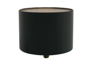
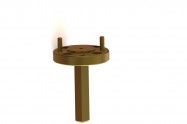
Probe Antenna View More
SECTION View More
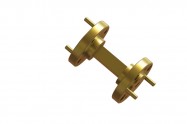
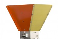
Double Polarization Horn Antenna View More
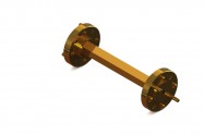
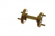
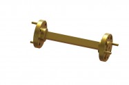
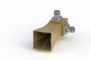
The use of ultra-wideband (UWB) antenna technologies for the UWB radar and communication systems in both military and civilian applications continues to increase, In some high power radar system, high gain and stable phase center is very important, and the ridged horn is very proper for this application. The dual-polarization system can get more information than the single-polarization antenna system; furthermore, the polarization modes at different directions using one radiation aperture make the structure more compaction. So realizing dual-polarization antenna by loading quad-ridged with proper feeding is very important. The quad-ridged horn antenna can employ the dual-polarization character.
The fabricated QRHA unit had an offset feed semi-rigid (50 Ω) coax to waveguide transition using a captivated coaxial female connector. The semi-rigid coax passes through the center of the ridge, and only the inner conductor is exposed in the ridge gap, which terminates in the alignment cavity present on the opposite ridge. A similar orthogonal probe is present for the other pair of ridges having a center to center offset with reference to the first probe.
Dual polarized horn antennas (quad ridged horn antenna) are offered as both standard and custom models with rectangular waveguide borders for both plane and vertical ports. Dual polarized horn antennas support the linear polarized waveforms.
Dual polarized horn antennas offer frequencies of 1GHz to 3GHz, 2GHz to 6GH-z, 6GHz to 18GHz, 18GHz to 40GHz, 22GHz to 44GHz with a nominal gain of 8-20dBi. The impedance of 50 Ohms. In Dual polarized horn antennas connections, the type is 2.92mm Connectors, SMA Connectors, or N connectors.
Double Polarization Horn Antenna
| Part No | Frequency Range(GHz) | Gain(dB) | Max VSWR | Maximum Continuous Power | Impedance | Connector | Cross Polarization Isolation |
| ODPA60180 | 6-18 | 8-13dB | <2.0:1 | 50W | 50Ω | SMA Connectors | >30dB |
| ODPA180400-20mm | 18-40 | 11-13dB | <2.0:1 | 50W | 50Ω | 2 -2.92mm Connectors | >30dB |
| ODPA180400-30mm | 18-40 | 13-15dB | <2.0:1 | 50W | 50Ω | 2 -2.92mm Connectors | >30dB |
| ODPA220440 | 22-44 | 15-20dB | <2.0:1 | 50W | 50Ω | 2 -2.92mm Connectors | >30dB |
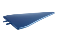
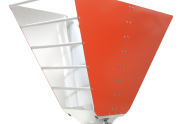
Log Periodic antenna View More
Biconical antena View More
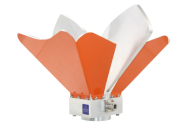
BICONICAL ANTENNAS
Biconical antennas. As an infinite structure, this antenna is truly broadband. However, its size and shape are impractical in real applications, and the truncation of its length limits its bandwidth performance. Modifying its rotationally symmetric shape to planar ones also causes a similar effect. Thus numerous design changes are considered and perfected to improve the modified antenna shapes and maintain the wideband characteristics.
The family of biconical antennas is generally broadband in input impedance. However, their radiation characteristics change with frequency. Therefore the design challenges are in maintaining the radiation performance satisfactory within their impedance bandwidth.
The biconical antenna is a simple modification of a dipole antenna, where the conductor thickness linearly increases with the distance from the origin or the antenna center. Mathematically, each arm of the antenna is an infinite conducting cone, and the geometry is a rotationally symmetric structure. In a symmetric biconical antenna the cone angles for the two arms are equal, as shown in FigureThe major difficulty with this antenna is its volume and especially its weight, which can be significant at low frequencies. The latter can be overcome by replacing the solid surfaces by wires, similar to other conducting surface antennas, like corner reflectors. Since for the fundamental TEM mode the induced currents on surface of this antenna travel in the radial direction, the conducting wires will be radial and the geometry will modify to the wire cones shown in Figure
The rotational symmetry of these structures can cause azimuthal mode excitations that can introduce cross-polarization. In practice, the number of cones is preferable to be eight or larger to minimize the cross-polarization effects. This means that every 45◦ a cone wire must be located. In the truncated cones, the sharp bends at the cone end cause severe impedance discontinuities, and thus reflections that cause the bandwidth limitations. These reflection effects can be reduced by tapering the cone ends, rather than truncating them. Each truncated cone, therefore, becomes a dual back-to-back cone. However, the end cones usually are made much smaller, as shown in Figure For the higher order modes, the currents will travel in both azimuthal and radial directions and the solid cones can only be replaced by wire meshes, to allow current flow in all directions.